Have you ever opened up a phone or remote and seen a little green board inside with lots of tiny parts? That’s a PCB, or Printed Circuit Board. It may not look exciting, but it’s a very important part of almost every electronic device. It helps all the parts work together by letting electricity flow through the right paths. In this guide, I’ll answer 20 simple questions to help you understand what a PCB is, how it works, and why it’s used. No tech knowledge needed — just a little curiosity!
- Part 1. What is a PCB in electronics?
- Part 2. What does PCB stand for?
- Part 3. What is the function of a PCB?
- Part 4. What are the types of PCBs?
- Part 5. How is a PCB made?
- Part 6. What materials are used to make PCBs?
- Part 7. What is the difference between a PCB and a breadboard?
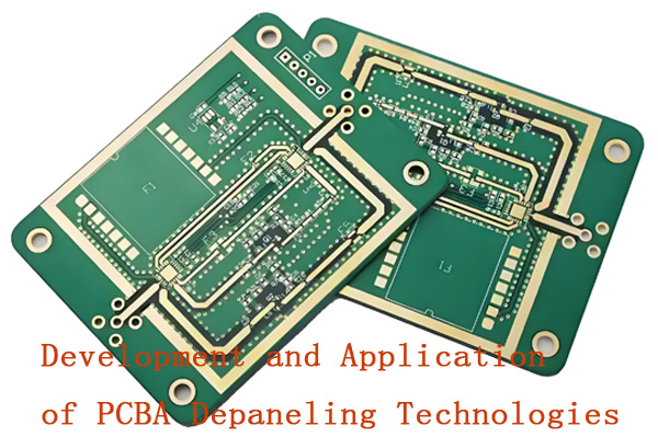
- Part 8. Why are PCBs green?
- Part 9. What are the layers in a PCB?
- Part 10. What are vias in a PCB?
- Part 11. FAQS about PCB
Part 1. What is a PCB in electronics?
A PCB (Printed Circuit Board) is a flat board that connects and supports electronic components using conductive tracks, pads, and other features etched from copper sheets. It’s the foundation of most electronic devices, allowing electricity to flow and circuits to function properly.
Part 2. What does PCB stand for?
PCB stands for “Printed Circuit Board.” It’s a non-conductive board that holds electronic components and uses copper traces to form electrical connections between them.
Part 3. What is the function of a PCB?
The main function of a PCB is to provide mechanical support and electrical connections for components in an electronic circuit. It organizes the layout of components and ensures stable, reliable signal flow and power distribution.
Part 4. What are the types of PCBs?
Common types include single-sided, double-sided, and multilayer PCBs. Others include rigid, flexible, and rigid-flex PCBs. Each type is suited for different applications based on complexity, size, and flexibility requirements.

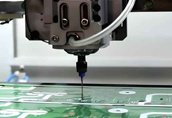
Part 5. How is a PCB made?
PCB manufacturing involves layering copper on a board, masking unwanted areas, etching the copper, drilling holes, applying solder mask, printing silkscreen labels, and adding surface finishes. Multilayer boards require careful stacking and lamination.
Part 6. What materials are used to make PCBs?
The most common base material is FR4, a flame-retardant fiberglass epoxy. Copper is used for conductive layers. Solder mask (usually green) protects the copper, while silkscreen ink labels component positions. Flexible PCBs use polyimide instead of FR4.
Part 7. What is the difference between a PCB and a breadboard?
A PCB is a permanent board with etched copper pathways for stable, durable circuits. A breadboard is a temporary platform for testing and prototyping, using holes and metal clips to hold components without soldering.
Part 8. Why are PCBs green?
PCBs are green because the solder mask — the protective coating over copper traces — is usually green. This color became standard due to historical manufacturing preferences and good contrast with white silkscreen for readability.
Part 9. What are the layers in a PCB?
PCBs can have multiple layers:
Substrate (base): Insulating board like FR4.
Copper layer: Conductive paths.
Solder mask: Protects copper and prevents shorts.
Silkscreen: Adds labels for components.
Multilayer PCBs have alternating copper and insulating layers.
Part 10. What are vias in a PCB?
Vias are small plated holes that connect different layers in a PCB. They allow electrical signals to pass vertically through the board. Types include through-hole vias, blind vias (outer to inner layer), and buried vias (between inner layers only).
Part 11. FAQS about PCB
What is a multilayer PCB?
A multilayer PCB has three or more layers of conductive copper, stacked and laminated together. It allows for complex circuits in a compact space.
What is the role of copper in a PCB?
Copper forms the conductive paths (traces) that carry electric signals and power between components on a PCB.
What are the advantages of using a PCB?
PCBs are compact, reliable, and durable. They reduce wiring errors, improve assembly speed, and support complex circuit designs.
What is PCB design?
PCB design is the process of creating the layout of components and copper traces using CAD software, before manufacturing.
What is PCB etching?
Etching removes unwanted copper from a PCB, leaving only the desired traces that form the circuit connections.
How do you identify components on a PCB?
Components are labeled with reference designators (like R1, C3) printed on the silkscreen, often matching a circuit diagram.
What software is used for PCB design?
Popular PCB design software includes Altium Designer, Eagle, KiCad, OrCAD, and EasyEDA.
What causes a PCB to fail?
Failures can be caused by overheating, moisture, cracked traces, poor soldering, or component defects.
What is the thickness of a standard PCB?
The standard PCB thickness is 1.6 mm (0.063 inch), but it can vary based on the application.
What is the difference between rigid and flexible PCBs?
Rigid PCBs are solid and inflexible. Flexible PCBs can bend and twist, making them ideal for compact or moving devices.
A professional with over a decade of experience in the PCB depaneling industry.